Payload
Project design
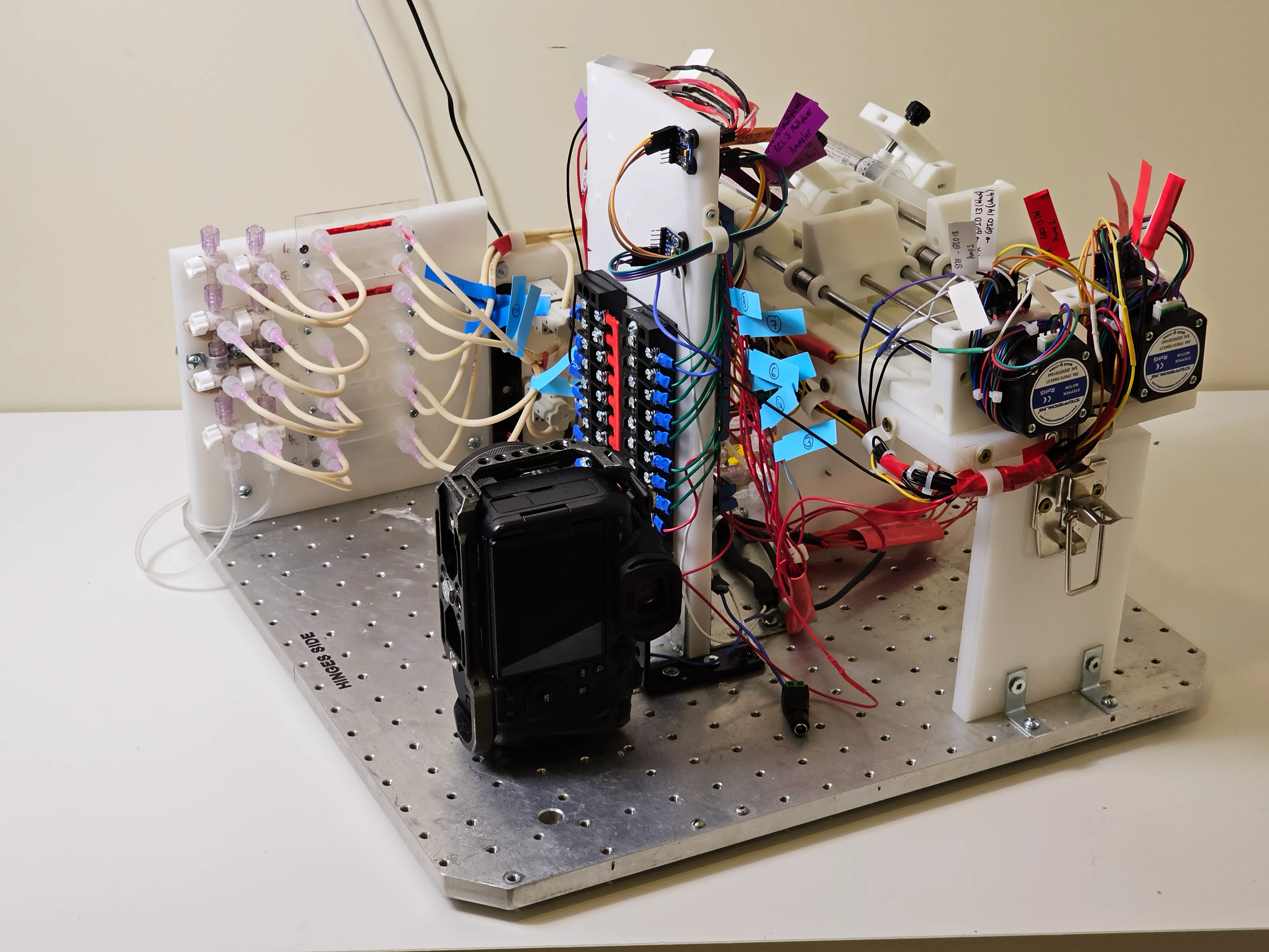
A closed-loop microfluidic system that perfuses a thrombolytic drug through clot-laden microchannels and measures the pressure change in real time — packed into a single flight case.
Everything lives inside a Pelican 0350 case. A Raspberry Pi 5 runs the experiment; the operator drives it over VNC from a laptop mounted on the case lid. Once the fluid is primed and the clots are formed, a full parabola takes two button presses.
That minimalism is deliberate. The usable science window is about twenty seconds long, the operator is floating, and anything that demands attention during those twenty seconds is a chance to lose the run. So the Pi automates all valve sequencing, pump control and logging, and the human commits to one decision: start now, stop now.
The payload divides into five subsystems — structure, fluidics, power, command and data handling, and imaging — described in turn below.
-
13.3 kg
Total mass
45 kg limit — 70.5% margin
-
190 W
Peak science power
1.91 A of a 5 A supply
-
8
Microfluidic channels
4 drug, 4 saline control
-
50 Hz
Pressure sampling
Minimum acquisition rate
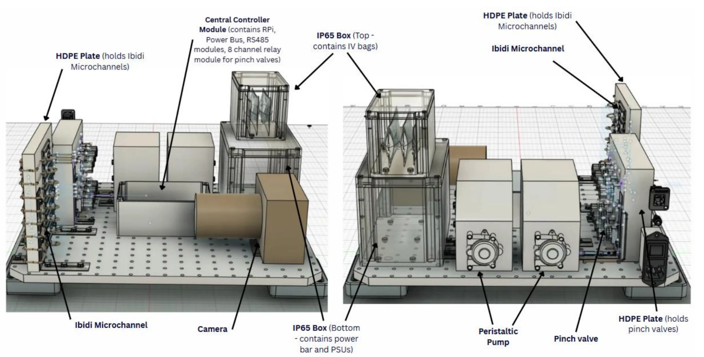
The layout
Inside the experimental platform
How it runs
Twenty seconds, two button presses
The usable science window is about twenty seconds long and the operator is floating. Everything that can be automated, is.
Flight profile
One parabola, three gravity regimes
Twelve parabolas across two flight days, flown in two sets of six with a five-minute level-flight pause between them. The science happens in the twenty seconds at the top.
- 01
T−2 s. The operator presses the button. The assigned pinch valve opens and the pump starts at its setpoint.
- 02
Microgravity. Fluid perfuses the clot. Both pressure sensors sample continuously and the camera records throughout.
- 03
Pull-out. A second press stops the pump and re-energises the valve, isolating the channel and returning pressure to baseline.
Fluid path
From reservoir to waste
The two sensor taps bracket the microchannel. Their difference is the pressure drop across the clot — and watching that difference collapse is watching the clot dissolve.
- 01 IV bag Drug or saline
- 02 Peristaltic pump 2.5 / 5.0 mL·min⁻¹
- 03 Sensor tap A Upstream pressure
- 04 4-way splitter To four channels
- 05 Pinch valve Normally open
- 06 ibidi µ-Slide Clot sits here
- 07 Check valve Prevents backflow
- 08 Sensor tap B Downstream pressure
- 09 Waste bag Sealed collection
Architecture
Five subsystems
Structure, fluidics, power, command and data handling, and imaging — each with the part numbers behind it.
Subsystem 01
Structure and mechanisms
The physical frame that has to hold every component in place through repeated 2 g pull-ups and pull-outs, twelve times a day.
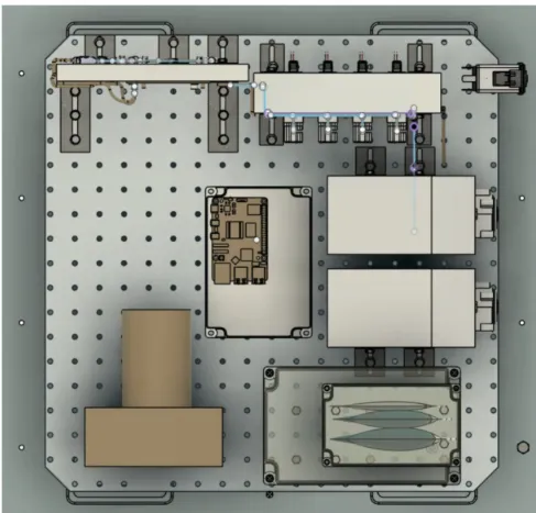
Every component bolts to a perforated aluminium baseplate through L- and U-brackets. Two HDPE sheets are cut as custom mounts: one holds the eight microchannels in a row where the camera can see them, the other carries the pinch valve manifold.
Three IP65 waterproof enclosures house the power electronics and the IV bags. The rating matters for a specific reason — this is a fluid experiment flying above other people’s equipment, and the enclosures plus the absorbent pads form a two-stage containment story that has to hold under 2 g.
Specification
- Baseplate
- Perforated aluminium, 45.5 × 45.5 cm Mounted inside a Pelican 0350 case
- Fixings
- L-brackets, U-brackets, M5 screws With lock washers throughout
- Custom mounts
- 2 × HDPE sheet Microchannel holder and pinch valve manifold
- Enclosures
- 3 × IP65 waterproof boxes Power electronics and IV bags
- Containment
- 3 × absorbent pad Secondary containment inside the case
Subsystem 02
Fluidics
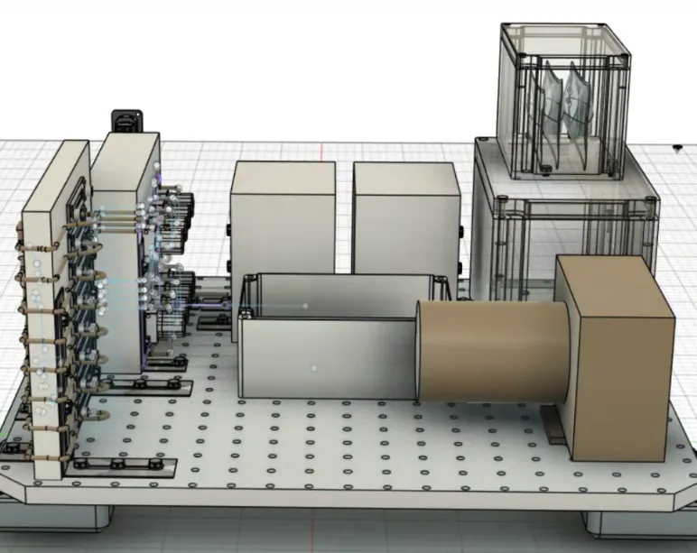
Two independent fluid paths — one carrying tenecteplase, one carrying saline — feeding eight clot-laden microchannels through individually addressable pinch valves.
The fluid path runs: IV bag → pump → sensor tap A → four-way Luer splitter → pinch valve → ibidi µ-Slide → check valve → sensor tap B → four-way splitter → waste bag.
The two sensor taps are the measurement. One sits upstream of the channel, one downstream; the difference between them is the pressure drop across the clot, and watching that difference collapse is watching the clot dissolve.
Valve choice carries a safety argument. The pinch valves are normally open, which means that when they lose power the tubes spring open rather than clamping shut. With the pumps also stopped, there is no driving pressure anywhere in the system and the fluid simply goes still. The failure mode is nothing happening — which, on an aircraft, is the correct one.
Clots are formed in place: porcine blood is loaded into each channel and recalcified with calcium chloride so it clots against the collagen-coated wall, the same morning as the flight.
Specification
- Pumps
- 2 × Kamoer M1-STP peristaltic Drug line and control line, independently driven
- Channels
- 8 × ibidi µ-Slide I 0.4 Luer Collagen-coated; 4 drug, 4 saline control
- Valves
- 8 × SMC LPV22-5K-T4A Normally-open solenoid pinch valves
- Reservoirs
- 2 × 100 mL IV bag, 1 × 250 mL waste Tenecteplase in normal saline; saline control
- Flow setpoints
- 2.5 and 5.0 mL/min Stability within ±5%
- Backflow protection
- 8 × one-way check valve Plus Y-site connectors merging to waste
Subsystem 03
Power systems
Aircraft mains distributed to four dedicated supplies, a 24 V bus for the valves and heaters, and a thermal loop holding the fluids at body temperature.
Power enters at 115 VAC through the emergency stop and a nine-way surge-protected bar, then splits to four dedicated supplies: the pump adapter, the Raspberry Pi PSU, the camera supply, and a 24 V rail for the valves and heaters. The 24 V rail is distributed through paired terminal blocks forming a positive and a negative bus.
A separate thermal loop keeps the tenecteplase and saline at 37 °C. Three waterproof temperature probes share a 1-Wire bus — one in the drug IV bag under PID control, one in the saline bag for logging, one on the drug tubing under PID control — with MOSFET switch modules driving the heater pads under PWM from the Pi.
The reason is straightforward: thrombolysis is an enzymatic process, and enzyme kinetics are temperature-dependent. Running the fluids at body temperature keeps the measured lysis rates physiologically meaningful, and holding that temperature constant means gravity stays the only variable in play.
Specification
- Input
- 115 VAC aircraft supply Through a hardwired E-stop to a 9-way surge-protected bar
- Pump supply
- 115 VAC → 24 VDC Pump 2 daisy-chained from Pump 1
- Controller supply
- 5 V / 3 A USB-C Official Raspberry Pi PSU
- Valve and heater supply
- ALITOVE 24 V 5 A (120 W) Distributed via two 12-position terminal blocks
- Valve switching
- ELEGOO 8-channel relay 5 V logic, active-low
- Thermal control
- 3 × DS18B20 on a 1-Wire bus PID on the drug bag and tubing; logging on saline
- Peak draw
- ~190 W / 1.91 A Against a 600 W, 5 A limit
Subsystem 04
Command and data handling
A Raspberry Pi 5 sequencing every valve and pump, reading both pressure sensors over I²C, and timestamping the result — with the operator reduced to two buttons.
The Pi drives eight GPIO lines into the relay module, one per pinch valve, plus two more into dedicated pump relays that close a dry contact across each pump’s foot-switch input — a deliberately dumb, hard-to-misfire interface.
Both differential pressure sensors sit on the I²C bus and are sampled continuously at 50 Hz or better. Every reading is timestamped and logged locally.
During a parabola: about two seconds before microgravity onset the operator presses Button A. That single command opens the pinch valve for the assigned channel and starts the corresponding pump at its setpoint. Fluid flows through the clot for the whole microgravity window and into the pull-out; a second press stops the pump and re-energises the valve, isolating the channel. Parabolas 1–6 run on Button A; 7–12 run on Button B against the second set of channels.
If something goes wrong there is a three-level response — reset the affected component in software, skip the channel for the rest of the flight, or pause all triggering and hold until the next level-flight period to diagnose.
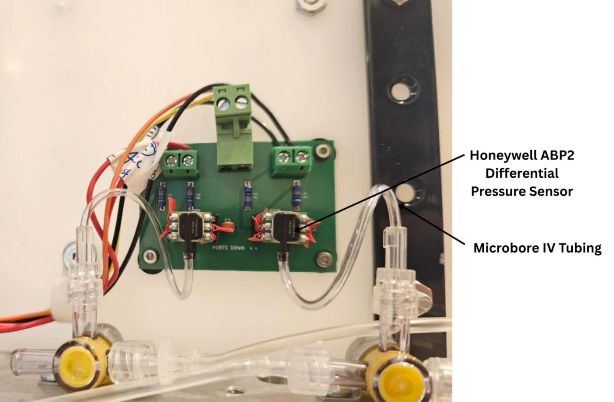
Specification
- Controller
- Raspberry Pi 5 Operator interface over VNC on Ethernet
- Pressure sensors
- 2 × Honeywell ABP2DRRT100MD2A3XX Differential, I²C, 14-bit
- Sensor range
- ±100 mbar (±1.45 psi) Total error band ≤ ±2% FSS
- Sampling
- ≥50 Hz continuous End-to-end latency under 0.2 s
- Valve control
- 8 × GPIO → relay module Active-low; LOW energises and pinches the tube closed
- Pump control
- 2 × GPIO → dedicated relays Dry-contact closure into each pump's foot-switch input
Subsystem 05
Imaging
A macro optical train recording the microchannels throughout each run, so that fragmentation events visible to the eye can be matched against the pressure trace.
Pressure tells you that a clot is dissolving. It does not tell you how.
A clot can fail gradually, eroding at the surface as the drug works through it, or it can fail suddenly, shedding a fragment that shifts downstream and changes the channel resistance in a single step. Those two produce different pressure signatures and have very different clinical meanings — a shed fragment is, in a patient, an embolus.
So the optical record is not decoration. It is the evidence that lets a step in the ΔP trace be read correctly, and it is why the camera runs continuously rather than triggering on events.
Specification
- Body
- Canon EOS R6 Mark II Mains-powered via adapter; battery as backup only
- Lens
- AstrHori 25 mm 2–5× ultra macro Resolves structure inside a 0.4 mm channel
- Illumination
- LED ring light Continuous, flicker-free at high frame rate
- Capture
- ≥60 fps capability Continuous through each parabola
- Monitoring
- USB tether to operator laptop Live view plus recording
Samples
Clots formed in place
In-vitro clots are made from porcine blood, recalcified with calcium chloride inside the collagen-coated microchannels so they form against the channel wall rather than being transferred in. Preparation happens the morning of each flight day: load the blood, add the calcium chloride, incubate, confirm the clot has formed.
All samples are classified Biosafety Level 1 / Risk Group 1. Used slides go into a sharps container post-flight; absorbent pads inside the case act as secondary containment.
Safety
Failure means nothing happens
A normally-closed emergency stop is hardwired into the case. Cut power — deliberately or otherwise — and the pumps stop dead while all eight pinch valves de-energize.
Because those valves are normally open, losing power opens the tubes rather than clamping them. With no pump running there is no driving pressure anywhere in the system, so the fluid simply goes still. On an aircraft, the safest failure mode is the boring one.
- Level 1 Software reset of the affected component
- Level 2 Skip the channel for the rest of the flight
- Level 3 Pause all triggering; diagnose at level flight